PRODUCT CATEGORY
CONTACT US
- Tel: 0086-311-89642206
- Fax: 0086-311-67906676
- Mobile: 0086-15076331069 13933856228
- E-mail: sales@hbmetals.com
- E-mail: info@hbmetals.com
![]()


 |
 |
 |
 |
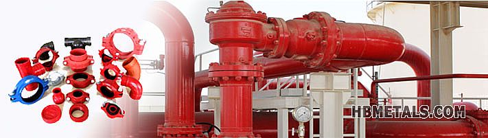 |
ANSI Flanged Single Sphere Rubber Expansion Joint
1. ANSI Flanged Single Sphere Rubber Expansion Joint 150LB
The "ANSI Flange" refers to two end flanges of the rubber expansion joints that are in compliance with ASME / ANSI B16.5. Since a rubber expansion joint is the weakest point of the pipeline, usually only low pressure rating 150LB flanges are applied as end connectors. "Single Sphere" refers to the shape of the rubber bellow which is also called "body" of a rubber expansion joint. There is also "Double Sphere Style" body available.

2. Materials for Single Sphere Rubber Expansion Joints
1) Rubber Bellow
Internal Rubber Core: EPDM, NBR, Natural Rubber, Neoprene, Viton.
External Rubber Cover: EPDM, NBR, Natural Rubber, Neoprene, Viton.
Fabric Frame: Nylon Tire Cord.
Reinforcement Ring: Steel Wire.
2) Loose Flanges:
Carbon Steel A105, S235JR, DIN St37.2 --- Flanges to be hot dip galvanized
Stainless Steel 304/304L, Stainless Steel 316 / 316L.
3. Technical Data Sheet - Movements of Rubber Expansion Joint
|
NPS
|
Maximum Allowable
Axial Movements |
Lateral
Deflection |
Angular
Deflection |
Torsional
Deflection |
||
|
mm
|
inch
|
Compression
|
Extension
|
(mm)
|
α(degree)
|
β(degree)
|
|
50
|
2"
|
10
|
6
|
16
|
18.1
|
3.0
|
|
65
|
2-1/2"
|
12
|
6
|
16
|
14.4
|
3.0
|
|
80
|
3"
|
12
|
10
|
16
|
12.5
|
3.0
|
|
100
|
4"
|
18
|
10
|
16
|
9.4
|
3.0
|
|
125
|
5"
|
18
|
10
|
16
|
7.5
|
3.0
|
|
150
|
6"
|
18
|
10
|
16
|
6.2
|
3.0
|
|
200
|
8"
|
25
|
14
|
16
|
6.9
|
3.0
|
|
250
|
10"
|
25
|
14
|
19
|
5.6
|
3.0
|
|
300
|
12“
|
25
|
14
|
19
|
4.7
|
3.0
|
|
350
|
14”
|
25
|
14
|
19
|
4.1
|
2.0
|
|
400
|
16“
|
25
|
14
|
19
|
3.4
|
2.0
|
|
450
|
18”
|
25
|
14
|
19
|
3.1
|
1.0
|
|
500
|
20“
|
25
|
14
|
19
|
3.1
|
1.0
|
|
600
|
24”
|
25
|
14
|
19
|
2.5
|
1.0
|
4. Technical Data Sheet - Dimensions of Flange Bolting & Joint Length
|
NPS
|
Face To Face
|
Outside Diameter
of Flange |
Number of
Bolts |
Bolt Hole
Diameter |
Diameter of
Bolt Hole Circle |
|
|
mm
|
inch
|
L(mm)
|
D(mm)
|
n
|
d0(mm)
|
|
|
50
|
2"
|
152.4
|
152.4
|
4
|
19.1
|
120.7
|
|
65
|
2-1/2"
|
152.4
|
177.8
|
4
|
19.1
|
139.7
|
|
80
|
3"
|
152.4
|
190.5
|
4
|
19.1
|
152.4
|
|
100
|
4"
|
152.4
|
228.6
|
8
|
19.1
|
190.5
|
|
125
|
5"
|
152.4
|
254.0
|
8
|
22.4
|
215.9
|
|
150
|
6"
|
152.4
|
279.4
|
8
|
22.4
|
241.3
|
|
200
|
8"
|
152.4
|
342.9
|
8
|
22.4
|
298.5
|
|
250
|
10"
|
203.2
|
406.4
|
12
|
25.4
|
362.0
|
|
300
|
12“
|
203.2
|
482.6
|
12
|
25.4
|
431.8
|
|
350
|
14”
|
203.2
|
533.4
|
12
|
28.4
|
476.3
|
|
400
|
16“
|
203.2
|
596.9
|
16
|
28.4
|
539.8
|
|
450
|
18”
|
203.2
|
635.0
|
16
|
31.8
|
577.9
|
|
500
|
20“
|
203.2
|
698.5
|
20
|
31.8
|
635.0
|
|
600
|
24”
|
254.0
|
812.8
|
20
|
35.1
|
749.3
|
Views: Author:hbmetals Date:15/03/05